


When we purchased our bus, we knew that it had a 30 Amp shore power connection, but to be honest we were not exactly sure what that meant. We knew it was smaller than 50 Amp (you know because 30 is clearly less than 50), but we soon found out that there is much more to it than that.
50 Amp shore power is more than just twenty more amps. You can actually pull 100 Amps at 120V from a 50 Amp shore power connection. This is because 50 Amp shore power is actually a 4-wire, 2-phase, 240 Volt connection with 2 hot 120 Volt legs that can each pull up to 50 Amps. Why don't they call it 100 Amp?
We went back and forth for a little bit about the decision to wire the bus for 50 Amps or 30 Amps. 50 Amps would give us more flexibility and obviously more usable power but at a higher cost. 30 Amps would install more easily with fewer and smaller gauge wires, and it would cost less, but it might be limiting if we decided to modify things in the future. In the end, we decided on 50 Amp, mostly due to the flexibility and "future-proofing" that it provides. The final push for choosing 50 Amp came when we ran across several blogs of bus owners who had wired their bus for 30 Amps only to regret it and rewire for 50 Amps later.
Transfer Switch vs Boosting Inverter
In a typical RV, shore power runs through a transfer switch to a breaker panel. If it is not connected to shore power, there will be an inverter on the other side of the transfer switch to make A/C power from the batteries. We, however, are not powering our bus through a transfer switch. We are using a boosting inverter.
Modern "boosting" inverters have changed the paradigm slightly. With "boosting" inverters, a separate transfer switch is not necessary. Instead, shore power is run through the inverter. One benefit of this type of inverter is that it can augment the current with power from the batteries in the event of a spike (like an air conditioner starting or microwave running). These boosting inverters act kind of like a UPS system on a computer, constantly monitoring the power usage and adding power from the batteries if the demand is greater than the available shore power.
For example, if we are plugged into someone's ordinary home outlet, we can limit the power to 15 Amps. If we go over that power limit (VERY easy to do), the inverter will pull the rest of the power from the batteries. The downside, of course, is that this means that we could completely deplete the batteries if we are drawing too much power, even when plugged in. However, if we are drawing less than the available shore power, any "extra" power that the inverter sees will go to charging the batteries.
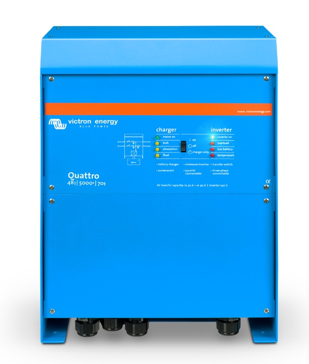
The inverter we selected for our build is the Victron Quattro 48/5000/70-100/100 120V VE.Bus
Components
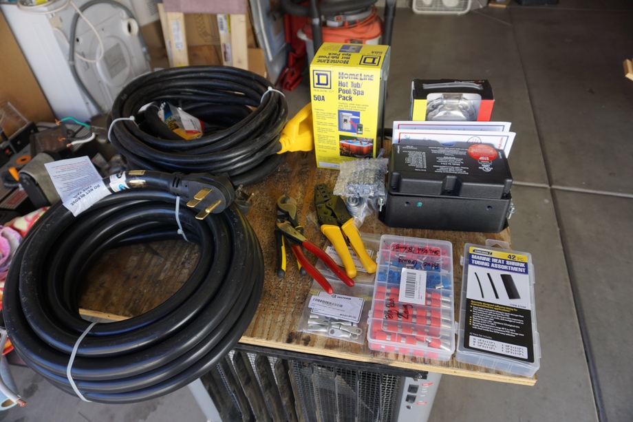 After deciding to go with 50 Amps and a boosting inverter, we needed to purchase all the materials to install shore power.
First, we chose a heavy-duty 30-ft 50 Amp cable with bare wires on one end and a 50 Amp NEMA 14-50 plug on the other side (we didn't actually need the plug).
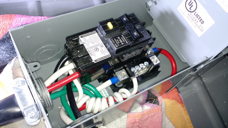
The manual that came with our inverter stated that we should put a circuit breaker on the incoming shore power (up to 100 Amps). Since we are running 50 Amps, it seemed logical to put in a 50 Amp circuit breaker.
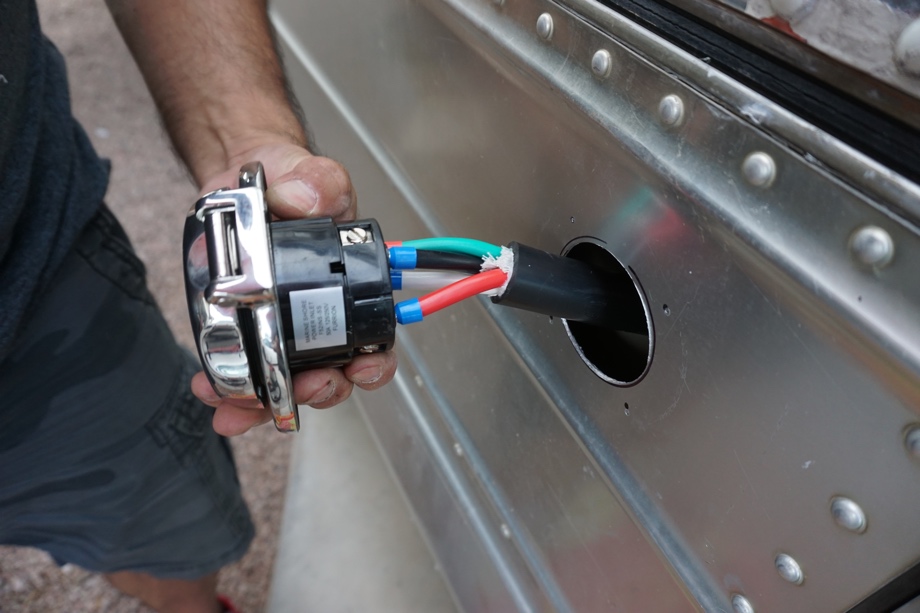
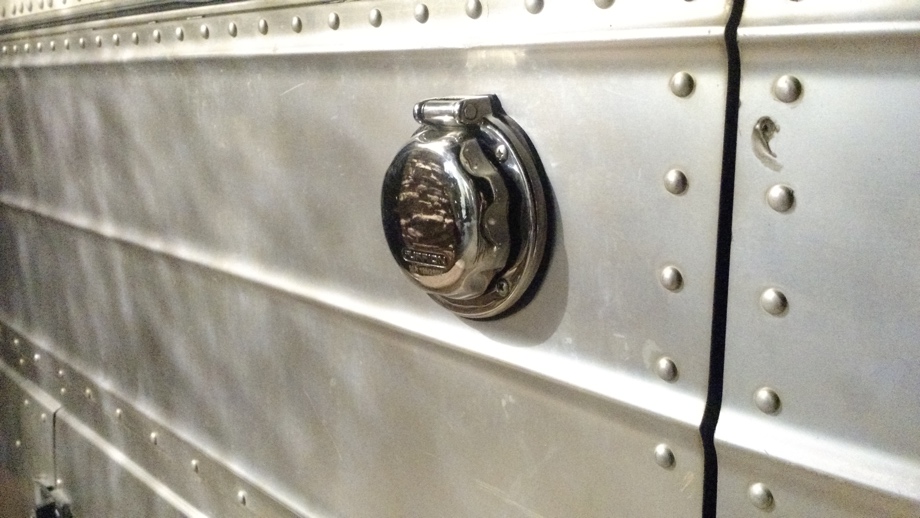
To plug in the bus, we opted to go with a 50 Amp "twist lock" power inlet (CS6465). Previously, the bus had been hardwired with a 30 Amp cable that passed through a plastic hole inlet to be plugged in. The new stainless steel marine grade inlet will definitely be an upgrade.
We also bought a shore power cable with a NEMA 14-50 plug on one side and a matching "twist-lock" 4-prong connection on the other side.
The last piece of the puzzle was a surge protector (more recently called an EMS surge protection device). After reading many reviews and watching a bunch of videos, we decided on the Progressive Industries EMS-HW50C. This is a "hardwired" unit, meaning it does not plug into the post like most traditional RV surge protectors and instead is neatly mounted in a bay. We chose this option because 1) we would not forget to use it and maybe blow something up and 2) we wouldn't forget to pack it away when leaving a campsite (or have it stolen).


Wiring It All Up
We started from the inverter and wired back to the power inlet. The first order of business was drilling a hole through the newly sealed battery bay. 
Then, we fed the wire through to the inverter and crimped on some 1/4 inch lugs. Next, we connected three of the four wires to our inverter.
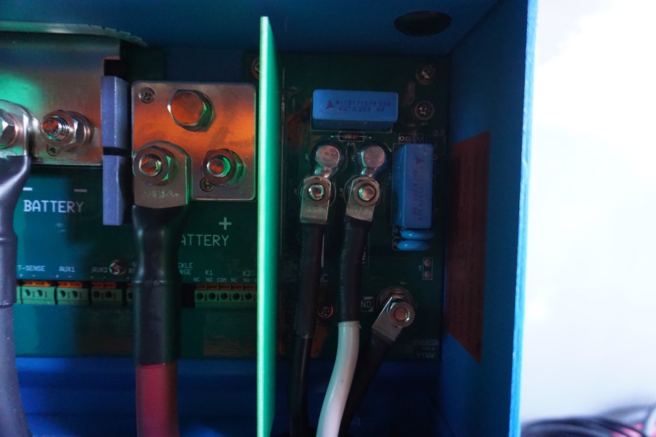 Our inverter does not have provisions for a 4-wire hook up with two hot wires, so we capped the unused hot wire (L2) with heat shrink. This keeps it safe and out of the way as well as allows it to be available in the future if we ever need it. Yes, that means that even though 50 Amps truly is 100 Amps, we are actually only using 50 Amps of it right now. In the event we ever want to use that other 50 Amp hot leg, we would have to either 1) add a second inverter or 2) wire that leg directly to a circuit breaker in which case we could only use that circuit when hooked up to shore power.
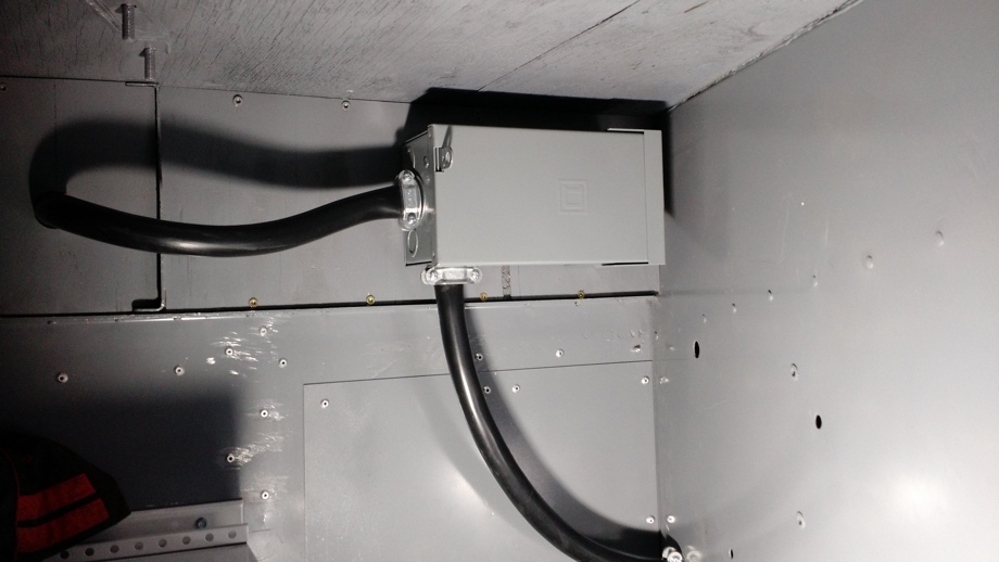
Next, we went to the other side of the wall and mounted the 50 Amp circuit breaker. We chose a spot high and out of the way. We wired the breaker and then passed the cable through the air conditioning bay, using some 1 1/4" service entrance connectors to keep things tidy and avoid damaging the cable on the metal walls.
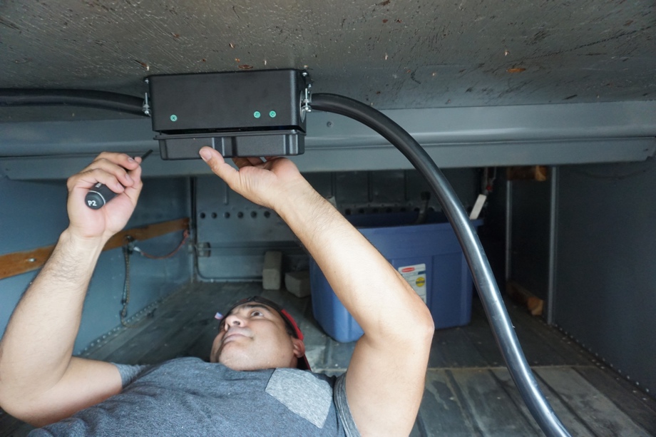
In the next bay (our pass-thru storage bay), we wired up the EMS surge protector and mounted it to the ceiling.
The final step was drilling a hole in the bay door and wiring and mounting the power inlet. We were sure to leave some slack in the cable, allowing the bay door to fully extend open.
Next steps: Installing a 50-Amp service at our house to allow system testing; Installing our breaker panel and running all of the a/c circuits
Watch the video:
Click here If you cannot see the video.

0 Comments
Comments powered by Disqus