

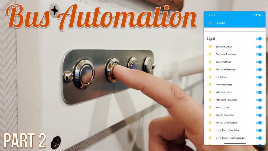
In our previous installment of our bus automation system, we space planned and installed most of the major components for controlling our lights as well as wired and tested the outputs for the lights. It is now time to share the input side (buttons to control the lights) as well as the installation and software that controls it all.
Layout
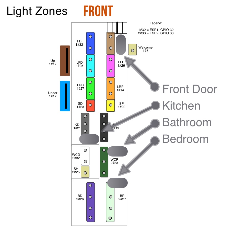
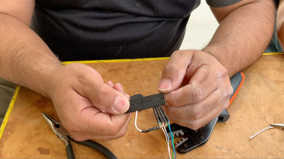
When we were building the bus, we knew more or less WHERE we wanted light switches but we were not 100% sure how many switches or how exactly they would work. Because many of the wires needed to go behind walls and through the ceiling, we needed to ensure we had enough wires to adequately control the lights. We also couldn't do "standard" light switches because our entire system is designed with the ability to be operated remotely so using a stateful switch would not work. We also did not want to run another processor in the wall or depend on things like the network for the switches to work. Fortunately, the buttons require very little power, so we opted to simply run an Ethernet cable (cat 6e) which gave us access to 8 little wires in a small package.
Planning
Using some help from "The Hookup" YouTube channel about which pins are best to use for input and outputs on an ESP32, we narrowed down which pins we would be using for inputs on our ESP32 boards.
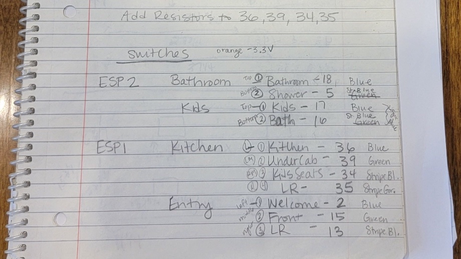
Because we had so many outputs on our first ESP32 board, we needed to use 4 pins (GPIO 36, 39. 34, 35) which can only be used as inputs and have a further limitation of not having any internal pull-up or pull-down resistors. Since we are using +3.3V to activate our switches, we needed pull-down resistors on these 4 pins. The only real way to take care of this is through an external circuit - fortunately, this is a pretty easy task so we mocked one up to be sure we could do it in such a small space. We tested it and it worked great! If you are interested you can read more about pull-up/pull-down resistors and how they work here or here.

Wiring the Buttons
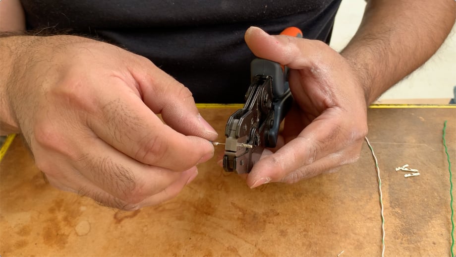
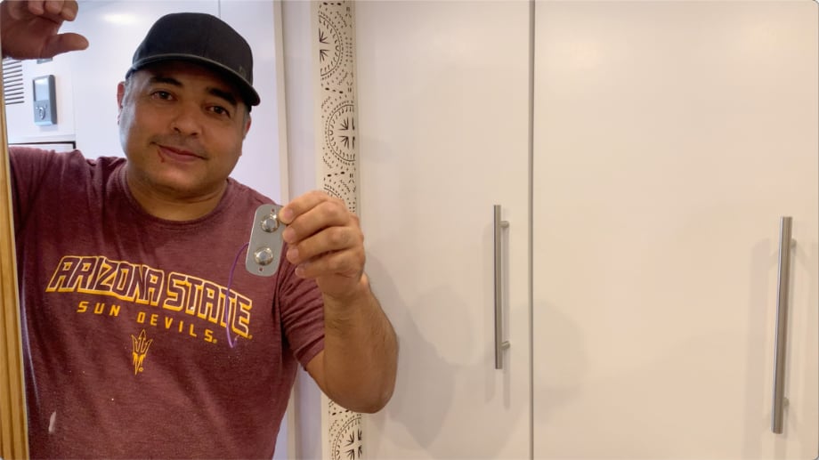
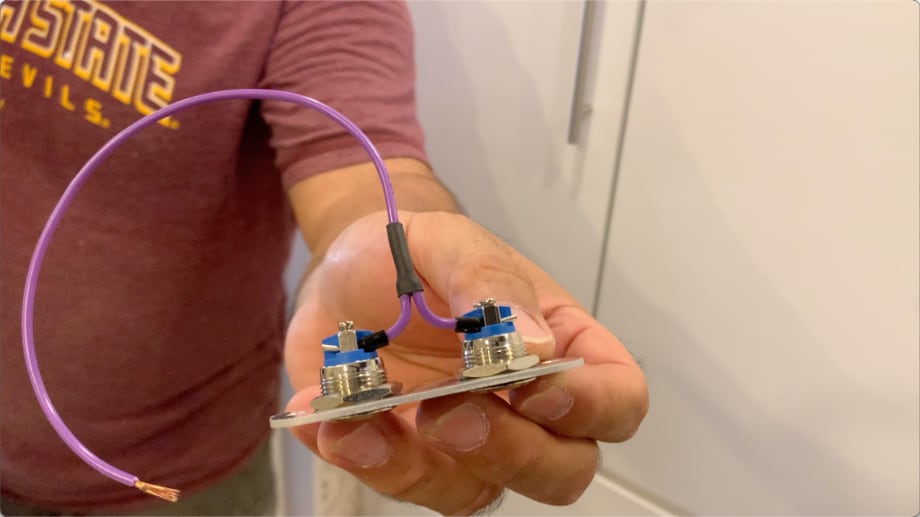
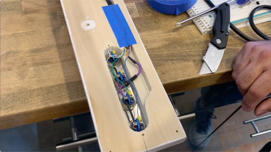
For the buttons, we went with some nice stainless momentary buttons from Amazon. We used some aluminum sheet stock we had from other projects to create some nice plates for the buttons. We then wired those up to the Ethernet cable we had run previously. On the technical side, we used the orange cable to supply the 3.3V needed to trigger the switches and generally blue/blue-stripe and green/green-stripe wires as the inputs from the buttons. We used ferrules on the wire ends to keep everything neat and snug.
Software
For home automation, we use Home Assistant. When we were initially testing everything, we used a Raspberry Pi 3 B+.
However, we always planned to eventually put it on a Docker image running on a Linux OS. We finally got around to transferring all the settings to an Ubuntu image. Recently we have started having a few issues as this is no longer a supported OS. If you are going this route do yourself a huge favor and just use Debian 11. That is what I will likely do in the very near future.
Code for the ESP32
When I last wrote about our bus automation project, I discussed MQTT and how to set up the code to manually listen for the events. This was great for the test project but ended up being a nightmare when you add in 20 independent lighting zones with 11 inputs. It was just far far too much manual coding and handling of events. Things got out of control pretty quickly and I figured there must be a better way. I had started implementing some of the home automation stuff in MQTT when I happened into a conversation with a friend, Scott, who also owns a GM PD-4106. He has been using Home Assistant for a while but is using ESPHome instead of writing the code manually. He insisted I could do all the tricky stuff I wanted to do with ESPHome so I started looking into it. WOW! ESPHome is an excellent piece of software! In just one afternoon I was able to get nearly every light in the bus working with the switches, dimming, and everything. To give you some perspective on how huge this is: I had been working on/off for 3 months to just get three buttons working with the manual way - and there was a bug I was dreading chasing down! We have now been running ESPHome for a solid 7 months and I couldn't be happier with the software.
One Year with this Setup
I can't believe it has been an entire year since we have put all this in! How has it performed? Amazingly well! After traveling over 15,000 miles this past year, we have not had a single glitch from any of the wiring or hardware we used. This is pretty amazing considering the low cost of everything involved. We have also expanded our home automation system for even more convenience. From our phones, we can now control fans in the tech cabinet, behind the refrigerator, and behind the convection microwave oven. We also have temperature monitors for about half a dozen places in the Bus. We can bring in data from our Victron equipment (really just experimenting at this point). We even built-in a leveling system that uses the airbags in our suspension to get the bus level when we are parked. With just a couple taps on our phone we can dump air from any corner of the bus and be perfectly level! Having access to all this control and information right from our phones has been extremely convenient and useful and we keep thinking of ways to expand the system to include even more!
What's Next?
We have only just started playing with the power of Home Assistant. We have what is essentially just a "stock" configuration with no customizations to the user interface. We have also not set up very much in the way of actual automation or scenes for some of the stuff we have automated. There is plenty of room to grow and customize but I feel like we have a very firm foundation to build from.
Watch the video:
Click here If you cannot see the video.


0 Comments
Comments powered by Disqus