

In our previous installment on bus automation, we had figured out how we were going to dim and control our lights using the ESP32 processors and some MOSFET boards we sourced from Amazon. We couldn't really use anything "off the shelf" (designed for home use at 120V AC) because we are operating and using 12V DC lights for our lighting. We wired the lights with this information in mind. Most notably, we wired the negative wires independently and all to the same location for central control. In our case, we wired them into the cabinet above the driver's seat.
After the lights were installed and the wires were run into that cabinet, we were ready to actually begin wiring all of this up to the ESP32s and MOSFET boards! Up until now, all this had been theory so now it was time to see if our plan would actually work! In part 1, we will be focusing on the output for our lights and space planning for our setup. In part 2, we will go into the inputs (buttons to turn the lights on) and how we actually set all this up in Home Assistant.
Layout
For our original layout, we have 18 "zones" defined for lights on the output side. On the input side, we knew we wanted 4 different switch locations: next to the front door, in the kitchen, in the bathroom, and in the kids' bedroom. Here is how we laid out our lights: Each color is a different zone with the circles being individual lights. The two lights on the side are strip lights.

Hardware
For our installation, we decided to use two ESP32 processor boards because of the large number of input and outputs required for running our lights. On a more technical note, the ESP32 has a dedicated processor for PWM switching which can support up to 16 independent PWM channels so we needed at least 2 processors for all the lights. For the dimming we have five four-channel MOSFET boards, giving us a total of 20 independent zones. We needed a 12Volt to 5Volt converter for power (Vcc), a 12 Volt fuse block, a few MOSFETs to handle the manual override function, and finally a switch panel with rockers to handle the manual override duties. To hook it all up we needed some Molex connectors that we got from Digi-Key:
- 19 pin connector for ESP32: Digi-Key Part# WM5353-ND - (Molex Part# 0050579319)
- Pins: Digi-Key part# WM2510CT-ND - (Molex Part# 0016020086)
- 3 pin connector for the MOSFET boards: Digi-Key Part# WM2901-ND (Molex Part# 0050579403)
We also needed some wire to hook this all up and we found that 22 AWG wire worked perfectly with these pins and connectors. We also needed the crimper for the small pins.
Planning
After a little research on which pins are best to use on the ESP32 for inputs and outputs with PWM in mind, we decided how to wire the outputs (you can see this on the layout diagram). We then decided how the ESP pins would connect with the MOSFET boards and wrote that down in our notebook.

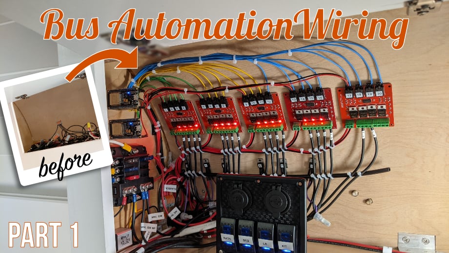
Installing and Wiring
After we had accounted for all the ESP32 pins and how they would be wired up, we tried to figure out how all the hardware would fit nicely in our cabinet. Once we had a good handle on that, we fabricated brackets and placed components where they needed to go. Next, we created the wires for the required circuits. For the ESP32 boards, we used the 22 AWG wire and the Molex connectors to connect to the MOSFET boards and power.


Final Thoughts
This was a tedious and somewhat fiddly project with all the tiny parts and wires, but we were really pleased with how it all turned out in the cabinet. Up next, we wire in the input switches and get it all working in Home Assistant. Spoiler - it's pretty awesome to be able to control and dim all the lights individually from our phones while lying in bed. :)
Watch the video:
Click here If you cannot see the video.


0 Comments
Comments powered by Disqus