


After making the decision to completely replace the 57-year-old defrost system with an aftermarket system, it was time to begin the installation. There were quite a few pieces and parts to map out: hoses, adapters, pumps, valves, cables, vents, and more hoses. Of course, it was not a simple drop-in replacement. Pieces needed to be fabricated, customized, and even 3D printed. Let’s dive in.
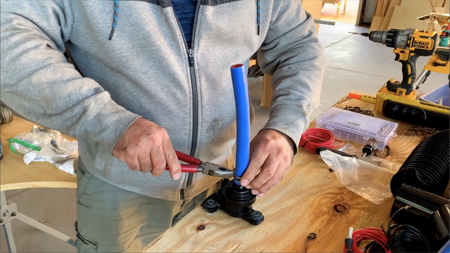
We started by cutting and piecing together all of the new silicone hoses. They are so nice to work with, especially compared to the rock-hard ancient rubber hoses we pulled out of there. Our Pex cutters came in handy for cutting the silicone hose. The original bus lines are ¾” and all of our new components are ⅝”, so we had to start off with some reducers. Unfortunately, the first reducers we tried leaked on the ⅝” side. They were just not really tight enough for ⅝” hose (even though that’s what size they said they were for). We ended up finding Dorman reducers at Autozone that worked great - no leaks!
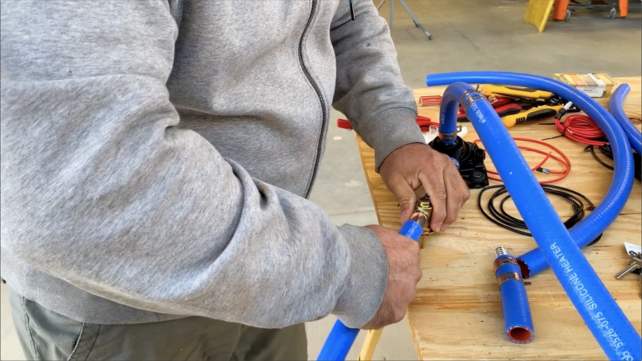
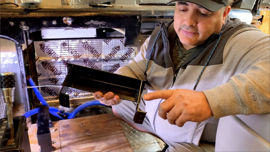
We cut, installed, and clamped up all of the new hoses to the small booster pump and the new temperature control valve. We then attached a push/pull control cable to the valve. Finally, we were able to clamp the new silicone hoses onto the main copper lines coming from the engine. Before we could move on, we had to address the fresh air intake.
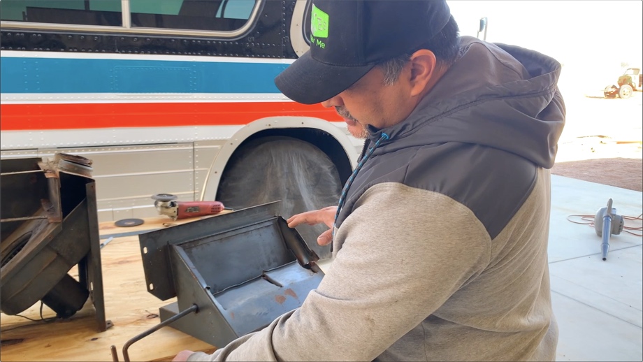
Part of the original defrost system was a manual vent flap that allowed fresh air into the blowers. It was part of that huge metal box that we removed last time, and it was in sad shape. In the process of trying to decide if we could reuse part of it and fabricate a new way to mount it, the main handle just broke off. We took that as our answer. Just like with everything else, we had to figure out a new solution.
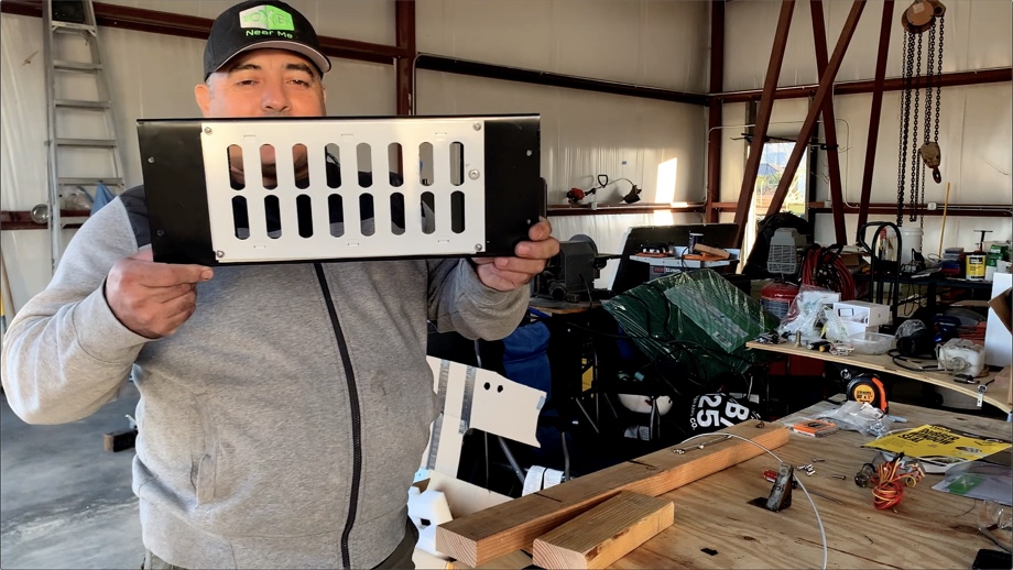
First, we cleaned up the vent inside the bus and put some rust-inhibiting paint on it. Then, we made a thin aluminum framework and attached a house foundation vent. It was just about the right size and could slide open or closed fairly easily. We just had to find a way to make the open/close work from the driver’s seat. We ended up drilling a hole in the sliding tab on the vent and attaching a push/pull control cable (just like for the temperature valve) that we mounted next to the driver.
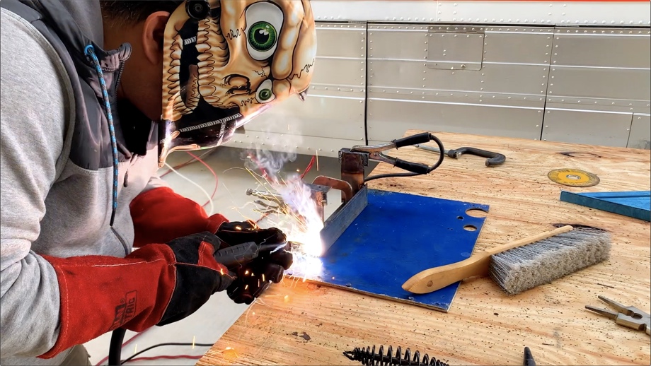
Before we could finally start to put it all together, we had to make some mounting stands for the actual heater box. It needed to sit high enough to make the hoses manageable, yet still leave us room above for all of the vent hoses. We used some scrap steel plate and angle iron to weld up stands that bridged over the hoses. Because the bus is aluminum, we did isolate the feet of our stands with small pieces of rubber in an effort to prevent dissimilar metal corrosion.
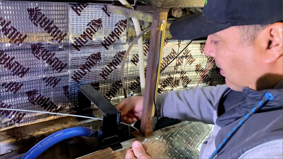
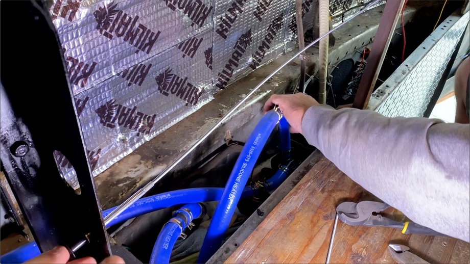
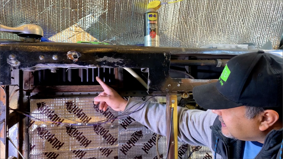
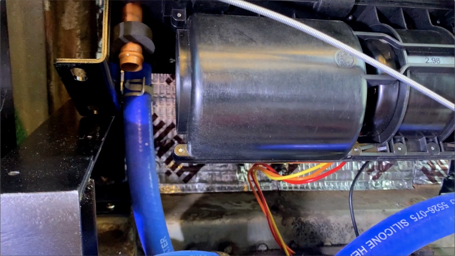
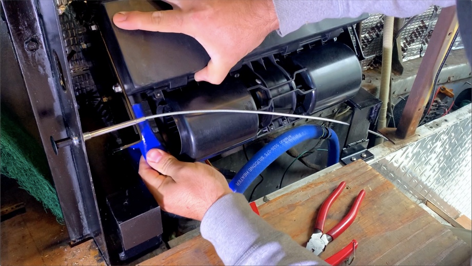
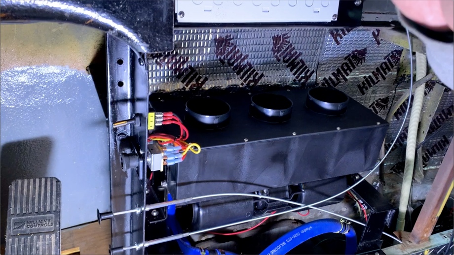
Finally, we were ready to start putting it all together. First, we mounted the pump in the recessed area below the heater. Then, we mounted the stands. Next, we set the heater box on the stands, carefully tilting it to reach the inlet and outlet lines. Very carefully and quickly, we connected the new hoses to the inlet and outlet of the heater. Last, we screwed the heater to our mounting stands.
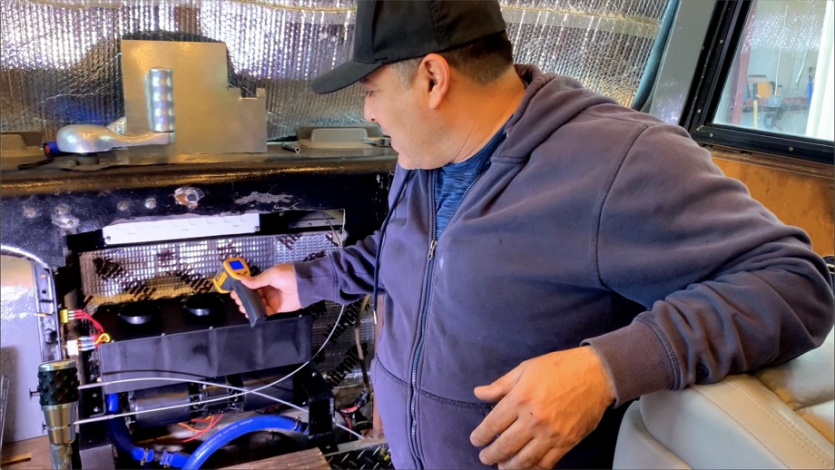
We quickly wired up the new defrost heater and a switch for the pump and it was time to test it all out. We filled up the coolant, and started up the bus. After letting it run for about ten minutes, the engine started to warm up just a bit and was around 135℉. We turned on the defrost and the pump and there were no leaks. The air was blowing out at about 115℉. The small pump was practically silent. We closed the temperature control valve, and the temperature of the air quickly began to drop. Within just a few seconds, it was down to 88℉. Perfect. So far, so good. We continued to check for leaks, and there were none.
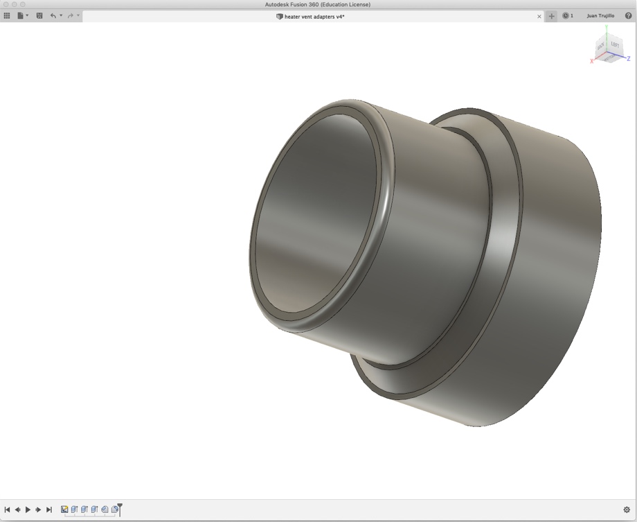
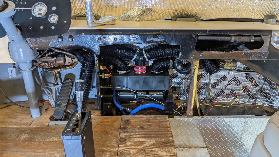
Everything worked great on that first trial run. Now we just had to do the vent hoses. Unfortunately, the size of the original bus defrost vents is a weird size - 2 ¾”. We bought a vent kit with 3” hose from the manufacturer of the heater. By the time we realized that we needed more hose (because we added some extra vents for the driver and passenger), everywhere was out of stock on that size hose. We ended up with 2 ½” hose, hoping we could make that work with the 2 ¾” vents. Turns out, that hose does not stretch that far. 3D printer to the rescue. We printed some small adapters out of ABS plastic to fit the 2 ½” hose on to the 2 ¾” vents. After giving the original bus vents a very thorough cleaning to eliminate over 50 years of dust, we finally were able to install all of those vent hoses.
Another test and everything was working great. We are so glad we ended up replacing the whole system. Besides not worrying about the old corroding metal radiator and nasty hoses, this new system is so much quieter. The old one was extremely loud. We also have all the controls right next to the driver. However, they’re all tied into one main “Defrost” switch on the side driver’s switch panel. All we really have to do is keep the heater on “Medium”, pump switch on, temperature control valve open, and air vent closed, and then just flip the one main “Defrost” switch and it comes on how we want it. If we want to change any of that, it’s simple enough to reach down and make an adjustment.
Next week, we finally get to show you how we covered up one of the last really ugly parts of the bus - all the chewed up metal of the front dash.
Watch the video:
Click here If you cannot see the video.


0 Comments
Comments powered by Disqus